EV Component Testing Challenges - From 12 to 800VDC
As the global interest for clean energy alternatives increases within the automotive industry, so does the requirement of efficiently storing electricity. The latest trends in electric vehicle technology have led to the development of high-voltage storage solutions, all backed by the need for increased efficiency and quicker charge times.
Starting with the traditional 12VDC lead-acid battery, one advancement was the 48-volt electrical system in mild hybrid electric vehicles (MHEV), which consists of an 48V lithium-ion battery in addition to a downsized 12VDC lead-acid battery. This advancement was driven to a large extent by the need to replace components that were traditionally mechanically-driven with more efficient electrical alternatives. It includes components such as electric power steering racks, electric transmission oil pumps, electric water pumps, electric brake vacuum pumps, etc.
Further development in plug-in hybrid vehicles (PHEV) and battery electric vehicles (BEV) has increased battery voltage levels to 300-400VDC. The very latest designs in the BEV sector are pushing that envelope even further to 800VDC, driven by the requirement of faster charging times and reduced wiring size and weight. There are however specific aspects opposing the further increase in battery voltage, such as semiconductor component breakdown voltage ratings, safety regulations (60–1500VDC is considered “high voltage”), cost challenges with connecting battery cells in series, etc.
Even in this current state, the need to test a portfolio of electrically-driven products with supply voltages ranging from 12-800VDC presents certain challenges. Let us analyze the example of electric coolant pumps. A typical design verification / product validation (DV/PV) test for this product type is the traditional 5-Point Functional/Parametric Check test (GMW3172 General Specification). This test verifies component performance through a combination of various supply voltage and temperature setpoints. For a 12VDC powered pump, this would require running a test using the Minimum Supply Voltage (Umin) of 9VDC, Nominal Supply Voltage (Unom) of 12VDC, and Maximum Supply Voltage (Umax) of 16VDC. In addition, it would require pairing these with the Minimum Operating Ambient Temperature (Tmin) of -40°C and Maximum Operating Ambient Temperature (Tmax) of +125°C. The combination of parameters would look something like the table below.
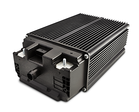
Continental HV DC/DC Converter
The same logic would apply for high-voltage systems, except the voltage spread (Umin-Umax) would be much higher. It is quite common for high-voltage battery systems to use DC-DC converters to step down the voltage to more traditional levels, allowing selection from a larger pool of more readily available hardware.
Let us consider the pump power rating next. Low power variants such as auxiliary electric coolant pumps usually operate in the 20-60W range. As such, they do not require a high current capacity since even with 12V architectures they will draw less than 5A. However main cooling pumps, which are used to displace traditionally mechanically-driven pumps, can be in the 300-1,000W power range for passenger cars. Continued use of the 12V architecture in these cases does not lend itself well due to high current draw requirement in order to satisfy the rated power.
The unit under test needs to be connected using copper wires, which have a resistance. Analyzing the scenario of powering a main cooling pump rated at 1,000W, using a traditional 12VDC battery the full-load current draw would be around 83A, whereas theoretically with a 350VDC system the current draw would be 3A. In the first case, the power supply would require use of 8AWG (8.4mm2) wire, whereas in the second case 16AWG (1.3mm2) wire would be sufficient. With a 15ft power lead length, the voltage drop across the power leads in the 12VDC case would be around 0.8VDC, while in the 350VDC case it would be around 0.2VDC. Due to the voltage drop being almost 7% of nominal in the case of the 12VDC architecture, it stipulates the need for using voltage sense leads to ensure the proper voltage level is delivered at the pump under test, rather than at the power supply sourcing that voltage.
Therefore implementing a test solution for the 12VDC architecture results in using thicker wire (more copper), which is more expensive, carries more weight, higher resistive losses, larger bend radius, etc. Additionally, it requires sourcing connectors with high current capacity, to allow interfacing to various component-specific electrical connectors. These connectors also require provision for transferring the pump control signal, usually in the form of either Pulse Width Modulated (PWM) signal or a Local Interconnect Network (LIN) signal. Simultaneously, both the electrical connectors and the cable/wire need to be able to meet the wide operating temperature range from the 5-Point Functional/Parametric Check test, making component selection exotic.
Solution
ATA’s modular solution of sourcing programmable voltage levels, measuring the corresponding voltage at the pump under test, and measuring the current draw, has solved the above challenges. The packages are available in various voltage/current combinations, ranging between 0-800VDC, 0-200A, and power envelopes of 300W, 800W, 1500W, and 3000W. The solutions are tested to deliver the level of performance, durability, and control stability that is inline with all major automotive OEM DV/PV test standards, and optimized to deliver the highest value in terms of cost.
Ensure™ is our out of the box solution for fluid & hydraulic component testing. Allow us to make your validation process easier and production line more efficient, with a bench mark test solution birthed from over 10 years of engineering experience.
8 AWG Wire
16 AWG Wire


